Fuel Cell Air-Independent Propulsion for Submarines
BLOGS
Vishwamitra
3/30/2026
For conventional submarines, Fuel Cell Air-Independent Propulsion has the potential to provide dramatically improved endurance, reduced acoustic and thermal signatures, and improved flexibility in mission execution compared to diesel-electric boats. However, for near-term programs, the baseline recommendation for a future Air-Independent Propulsion plant would be a Proton Exchange Membrane Fuel Cell-based plant with a battery buffer and power electronics. Realistic program goals for a future patrol submarine would be to provide a continuous power band in the 100-300 kW range, with peak battery power available for tactical sprinting. For a plant in the 200-250 kW range, sized to provide power for 14-21 day low-speed endurance, reactant storage would dominate the plant mass and volume requirements, affecting plug sizes and infrastructure. Program priorities would include modularity, acoustic and thermal signature control, reactant storage R&D, and shore infrastructure for handling hydrogen and oxidizers.
Top‑level requirements:
Endurance target: 14–21 days submerged at patrol speed.
Continuous power band: 100–300 kW.
Peak power (battery bursts): 2–4× continuous for short durations.
Hotel load assumption: 10–30 kW continuous.
Acoustic threshold: meet or exceed current quiet conventional submarine benchmarks.
Thermal threshold: no localized IR plume detectable at typical ASW sensor ranges.
Safety constraints: certified handling for H₂/LOX or approved reformate procedures.
Why fuel cells for AIP?
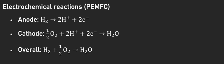
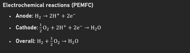
Fuel cells are attractive power generators as they convert chemical energy to electricity with high efficiency and very low mechanical noise since they have few moving parts. Moreover, PEMFC has a low operating temperature, a fast start time, and a modular scale. These characteristics make PEMFC a good candidate for AIP since response speed, compactness, and low noise are key factors in submarine AIP applications.
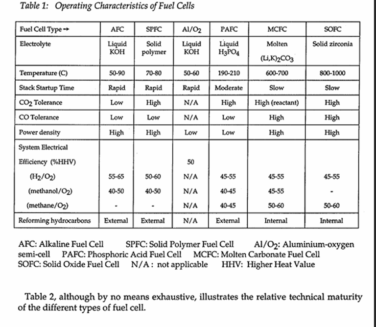
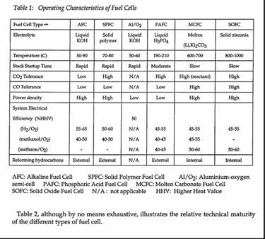
Candidate Fuel Cell Types and Basis of Choice
PEMFC (SPFC) Baseline:
Temperature: 60-80°C
Fast start
High power density
High purity hydrogen required
Water: main byproduct
AFC (Alkaline Fuel Cell)
Good performance
Sensitive to CO₂
Requires very pure gases
SOFC (Solid Oxide Fuel Cell)
High efficiency
Flexible fuels
Slow start
High temperature: 600-1000°C
Heavy BoP
Not suitable for AIP
MCFC/PAFC
Higher temperature
Niche applications
Complexity: temperature management
Not suitable for AIP
Performance Anchors
Stack Efficiency: 45-55% (LHV) for typical PEMFC systems in naval BoP applications.
Stack Modularity: Design stacks to be replaceable units with a power output of 25-75 kW.
Start Time: Minutes to tens of minutes depending on thermal management and preconditioning.
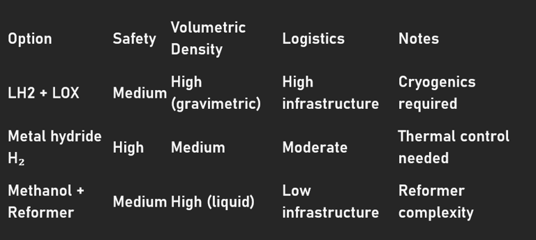
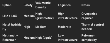
Compressed or Liquid Hydrogen + LOX
Pros: Best gravimetric energy density; high purity; simple electrochemical reaction.
Cons: Cryogenic handling for LH2 and LOX; requires specialized infrastructure on the shore side.
Metal Hydride Hydrogen Storage
Pros: Easier handling and near-ambient pressure storage; good volumetric density.
Cons: Heavy; requires thermal management for hydrogen extraction; refurbishes hydrogen beds periodically.
Liquid Fuel + Onboard Reformer (e.g., Methanol)
Pros: Utilizes existing liquid fuel infrastructure.
Cons: Lower system efficiency; CO and CO2 management; additional BoP and complexity for the reformer.
Sizing anchor example (design anchor)
Plant: 200-250 kW PEMFC running continuously.
Endurance: 14-21 days at low patrol speeds (3-6 knots) implies reactant energy on the order of tens of MWh; reactant mass/volume usually dominates plug sizing.
Implication: select storage approach based on logistics and/or platform constraints; metal hydrides for safety, LH2 for mass performance if shore facilities are available, reformate for logistics.
Balance of Plant (BoP) essentials
Humidification and water management for PEM membranes.
Heat exchangers for low-grade waste heat rejection without detectable thermal plumes.
Pumps, compressors, valves for reactant delivery; acoustic isolation necessary.
CO cleanup (methanol reformate) necessary for catalyst protection.
Power Architecture
Topology: DC bus with bidirectional converters for fuel cell, battery, and motor drive.
Battery buffer for handling transient loads and silent sprinting; also for smoothing fuel cell loads and running at optimal efficiency.
Modular stacks and redundant reactant supply for graceful degradation.
Signature Management
Acoustic: mount pumps/compressors on resilient mounts; use low-speed, high-torque motors; minimize piping noise.
Thermal: spread heat rejection across multiple hull locations; use seawater heat exchangers with low-signature discharge.
Exhaust: dissolve or chemically treat CO2/exhaust plume to prevent bubble trails; consider CO2 scrubbers/dissolvers with associated energy costs.
Retrofit vs. new-build integration
Retrofit: plug insert approach; trim, ballast, and structural reinforcement planning are critical.
New-build: dispersed integration, layout optimization, and shared systems for maximum mass-volume efficiency.
Representative mission profiles
Silent patrol: continuous AIP operation at low speed (3-8 knots) to maximize endurance. AIP output: 100-200 kW. Endurance: weeks, depending on reactant masses.
Transit with AIP assistance: AIP provides hotel and propulsion support to reduce diesel consumption during long transits.
Tactical sprint: battery-only propulsion for high-speed operations at speeds above 20 knots. AIP charging batteries during low-speed operations.
Emergency surface: diesel generator for extended recharging during surfaced or snorkelling operations or for high-speed operations.
Performance relationships (numerical anchors)
Speed vs. power: propulsion power increases with the cube of speed. Thus, small increases in speed have a major impact on endurance.
Endurance vs. reactant mass: endurance increases linearly with reactant masses. Thus, doubling the reactant masses roughly doubles endurance, within hull and buoyancy constraints.
System efficiency: system efficiency depends on stack efficiency, BoP losses, and battery round-trip efficiency. The system electrical efficiency can be in the range of 35-50% for reformate-based systems and 40-55% for direct H2/LOX-based systems.
Operational doctrine
Refuelling cadence: plan refuelling intervals based on mission tempo and available resources.
Emergency procedures: quick isolation of reactant systems, inerting of compartments, and safe venting routes.
Maintenance windows: plan stack inspection, catalyst checks, and hydride bed servicing during planned dock periods.
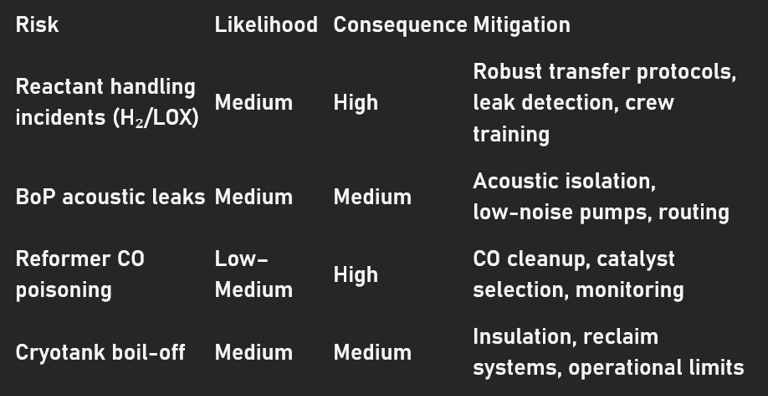
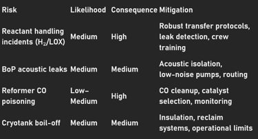
Safety systems and procedures
Continuous monitoring of gases (H₂, O₂, CO) with automatic isolation and alarm.
Inerting and ventilation strategies for storage and processing compartments.
Emergency venting and blast relief design for storage bays.
Crew training and certification of transfer operations for shore/tender operations.
Certification and test program
Shock and vibration testing of tanks, stacks, and BoP.
EMI/EMC testing of power electronics and control systems.
Cryogenic handling certification of LH2/LOX systems.
At-sea acceptance trials, endurance runs, signature measurement, and emergency drills.
Top programmatic recommendations
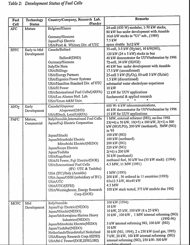
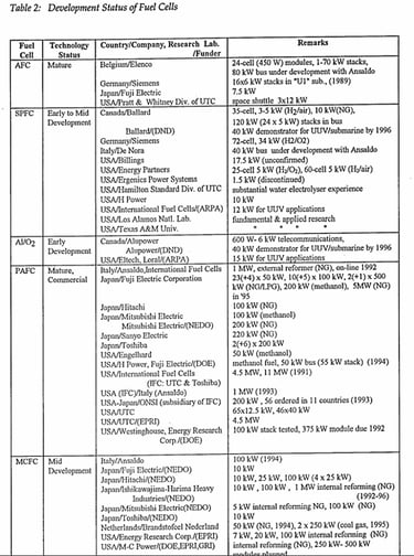
Adopt PEMFC baseline for near-term AIP programs; AFC should be considered only with guaranteed reactant logistics.
Design modular stacks and power electronics for incremental upgrade and "at sea" swaps.
Invest in reactant storage R&D (metal hydride, LOHC) and shore infrastructure for LH2/LOX, if selected.
Acoustic and thermal isolation should be integrated early in hull and system design.
Develop a strong safety and refuelling doctrine with certified shore and tender operations.
Establish a test plan with shock, EMI/EMC, cryogenic, and "at sea" acceptance trials.
Perform mission-level trade studies to compare endurance, mass, volume, and logistics of various reactant options.
Plan for life cycle costs, including catalyst replacement, hydride refurbishment, and cryotank maintenance.
Standardize interfaces to enable cross-platform module swaps between platforms.
Involve industry early to conduct vendor maturity assessments.
Major cost drivers
Reactant storage system and shore infrastructure costs.
Balance of Plant (BOP) complexity, including reformers, humidifiers, and heat exchangers.
Catalyst and stack replacement costs over life cycle.
Acoustic and thermal isolation costs.
CASE STUDY
DRDO’s Air Independent Propulsion System for Submarines
It seems a decision has been taken by the Indian Navy (IN) to install an air‑independent propulsion (AIP) system developed by the Naval Materials Research Laboratory (NMRL), Ambernath, which is a part of the Defence Research & Development Organization (DRDO), on all six of its Scorpene class diesel‑electric submarines once they become due for their first major refit. This decision is of course contingent upon NMRL’s AIP being fully proven by then as a ‘safe plug’. Given that the refit of even the first Scorpene Class submarine, the INS Kalvari, is not due for at least another six years, NMRL is confident of having refined its already advanced prototype sufficiently by that point, to satisfy IN’s requirements.
The earlier plan of installing NMRL’s AIP on the last two Scorpenes has been given up since NMRL’s AIP plug was not deemed sufficiently mature by the original equipment maker (OEM) of the Scorpene Class, France’s Naval Group, once known as DCNS. As such, it is felt by various stakeholders that it is now too late to install the AIP on the last two Scorpenes which are also at an advanced stage of construction.
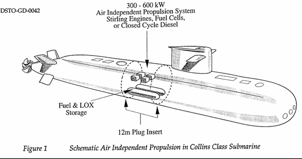
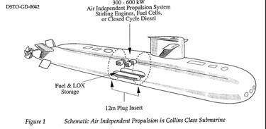
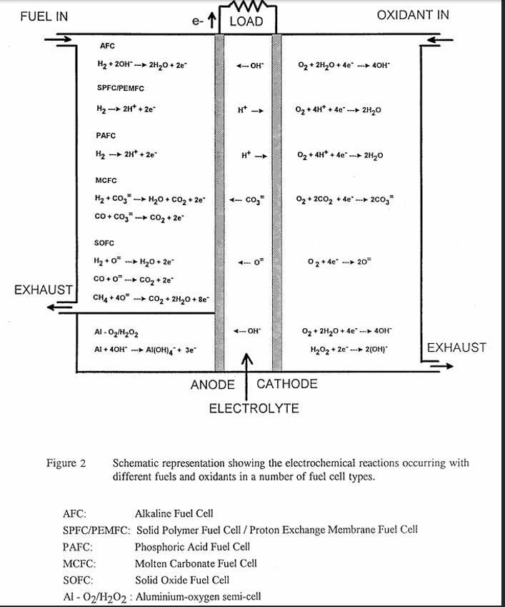
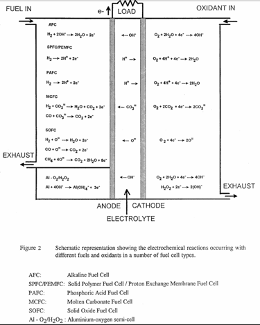
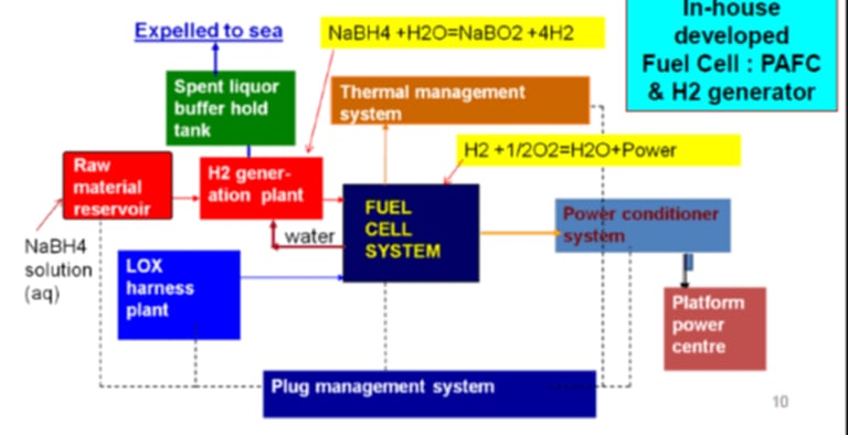
However, IN has decided that even though the process of installing the AIP plug during refit will involve cutting open the hull of its Scorpene units, it would still be worth it, given that NMRL’s AIP boasts attractive features. In fact, NMRL believes that its Phosphoric Acid Fuel Cell (PAFC) based AIP solution is a step ahead of what the People’s Liberation Army Navy has obtained from Sweden in the form of a Stirling cycle-based AIP for its submarines. Be that as it may, let us take a closer look at NMRL’s 250-kilowatt (kW) PAFC based AIP solution that allows up to 14 days of underwater endurance for a submarine running solely on power supplied by this system. Fig. 1 below gives the overall scheme behind NMRL’s AIP system.
On‑board hydrogen generation
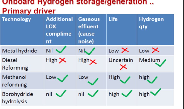
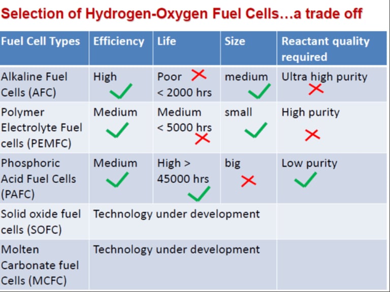
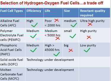
While based on a proven fuel cell technology type i.e PAFC, NMRL’s AIP system, nonetheless, incorporates a set of innovations that make it a rather contemporary system. For one, NMRL’s AIP package has an onboard hydrogen generation plant, which produces hydrogen ‘in situ’ unlike many other AIP configurations where hydrogen for a mission has to be carried on board. Moreover, on board hydrogen production in NMRL’s AIP does not require any kind of combustion. NMRL’s AIP supplies hydrogen ‘in situ’ by reacting hydrogen ‘rich’ sodium borohydride, which is carried on board, with water, to generate hydrogen and sodium metaborate (see Fig. 1, above). The advantages of this kind of ‘borohydride hydrolysis’ (BH) to generate hydrogen vis a vis other forms of on‑board hydrogen generation are given below in Fig. 2. NMRL’s BH process generates a considerable amount of hydrogen without entailing the release of any gaseous effluents which add to system noise and can compromise submarine stealth. Moreover, BH plants also have long operational lives.

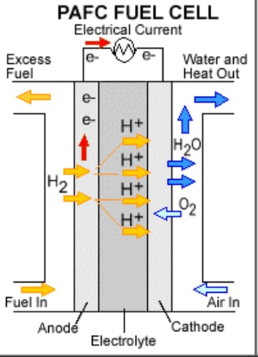
PAFC innovation
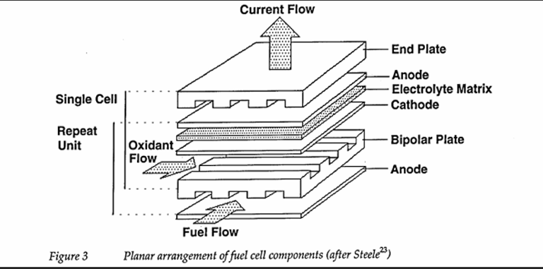
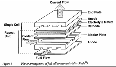
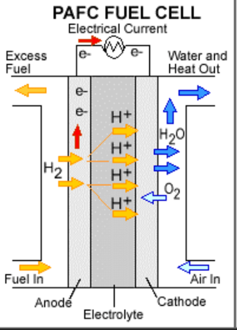
Now the hydrogen generated by BH is sent to the main power plant of the AIP system which is made up of PAFC stacks, which of course use phosphoric acid as an electrolyte. The electrodes of NMRL’s PAFC design are made of PTFE bonded platinum/ carbon. The electrode support is in the form of carbon paper and silicon carbide serves as the electrolyte support. A typical PAFC layout and process is depicted in Fig. 3 below.
PAFC background and NMRL innovations.
PAFCs are a mature commercial fuel‑cell technology noted for long service life and tolerance to reactant impurities—attributes that reduce hydrogen‑purity burdens compared with reformate systems. NMRL has ruggedized PAFC stacks for marine use by developing PTFE‑bonded Pt/C electrodes on carbon‑paper supports, silicon‑carbide electrolyte supports, corrosion‑resistant materials, and acid‑management systems. The lab has patented improvements (catalysts, sealants, acid holders) and trialed siloxane‑based microporous gels to improve water retention and reduce stop/start degradation. NMRL reports a lower operating temperature versus legacy PAFCs, which reduces parasitic loads and increases net propulsive output.
Indigenous production
Importantly, NMRL’s development of indigenous PAFC stacks has been done in close cooperation with Indian industry. In fact, NMRL developed PAFCs are the first examples of successful industrialization of any FC type in India. NMRL has transferred PAFC technology to Thermax Ltd, Pune which began production with the supply of twenty‑four 3 kW PAFC units for captive use at NMRL via a buy back arrangement. According to CSIR, Thermax’s facility ‘is provided with all sub‑manufacturing modules to manufacture electrodes from basic raw materials, assemble them in the form of fuel cell stacks and conduct elaborate testing of each stack for meeting the strict quality control requirements of NMRL necessary for defence establishments. It seems that large scale skilled manpower for the manufacture of fuel cells has also been developed in the course of industrializing NMRL’s PAFC technology.
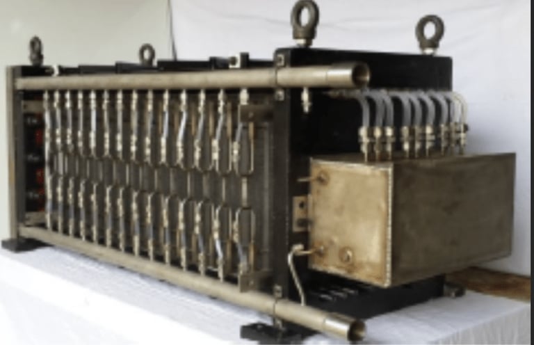
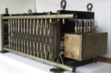
NMRL and Thermax have now graduated to the production of the N11, 11.5 kW marine grade PAFC stack shown below that has a rugged cocoon structure and has passed shock and vibration tests that one may experience during intense underwater operations. Such parallel / series connected PAFC stacks can be used for power generation levels of up to 500 kW, thereby underlining the modularity of NMRL’s AIP solution which can be used in submarines other than the Scorpene as well. Such parallel/series connected N11 modules can scale to ~500 kW and allow the control system to reconfigure around failed modules, increasing survivability.
For the Scorpene and beyond
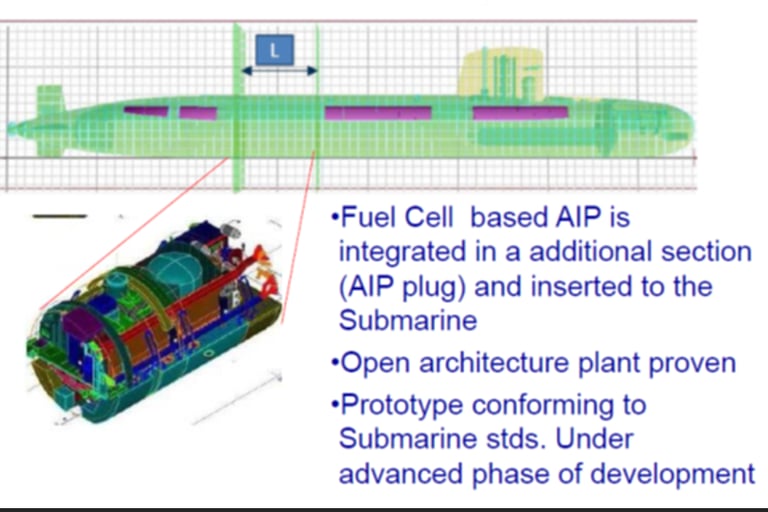
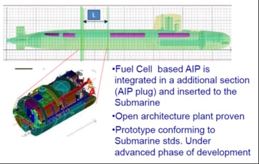
The current AIP prototype being tested at NMRL has been optimized for the form and fit of the Scorpene’s hull (see Fig. 6 below), although modules that fit other hull dimensions can be engineered as well.
BoP implications
NMRL’s choice of PAFC + NaBH₄ impacts the BoP profile: add pumps and associated control for the hydrolysis plant, spent liquor handling systems, and acid management systems for the PAFC stacks. Additional parasitic loads for hydrolysis heating and spent liquor handling are expected; design the heat management system and heat exchangers to minimize localized IR signatures.
Refit logistics and program timeline.
Retrofitting Scorpene boats requires hull cutting and insertion of a neutrally buoyant plug sized to platform constraints; design must account for plug length, trim and ballast adjustments, and tender/shore procedures for NaBH₄ resupply and spent‑liquor offload. Use the Scorpene refit schedule as a controlled maturation path: complete land‑based qualification, shock and vibration testing, harbor acceptance, and at‑sea trials before the first refit. Maintain contingency options (compressed H₂ or reformate) if certification timelines slip.
This AIP conforms to the typical standard that its length be less than 10 percent of the hull it is intended for and is a cylindrical plug that is neutrally buoyant and probably weighs less than 300 tons. Obviously, NMRL’s AIP has got no heavy rotating machinery and NMRL is confident that the module ‘maintains relative silence and retains its stealth characteristics’ throughout the platform’s envelope.
As such, the development of an indigenous AIP system by DRDO and its complete domestic industrialization is a significant milestone in the development of FC technology in India. Apart from the Scorpene programme, whatever diesel‑electric submarine design is chosen for construction under Project‑75I is also likely to be a recipient of NMRL’s AIP solution.